

A track recording vehicle once had to visit a line before anyone knew its geometry had drifted out of tolerance — today, a passenger train running its normal schedule can report the same defect while still in service.
That change in habit is what this section is about. A depot technician checking bearings, a laser scanner reading rail profile, an accelerometer riding an axle box in commercial traffic — all of it is measurement, and all of it now runs continuously rather than at fixed intervals.
What replaced the inspection round
Conventional railway maintenance has depended on scheduled inspection: a track recording vehicle surveys a route at defined intervals, a depot technician checks bearings, a maintenance crew measures rail profile geometry. These methods remain essential, but each produces a snapshot valid only for the moment it was taken.
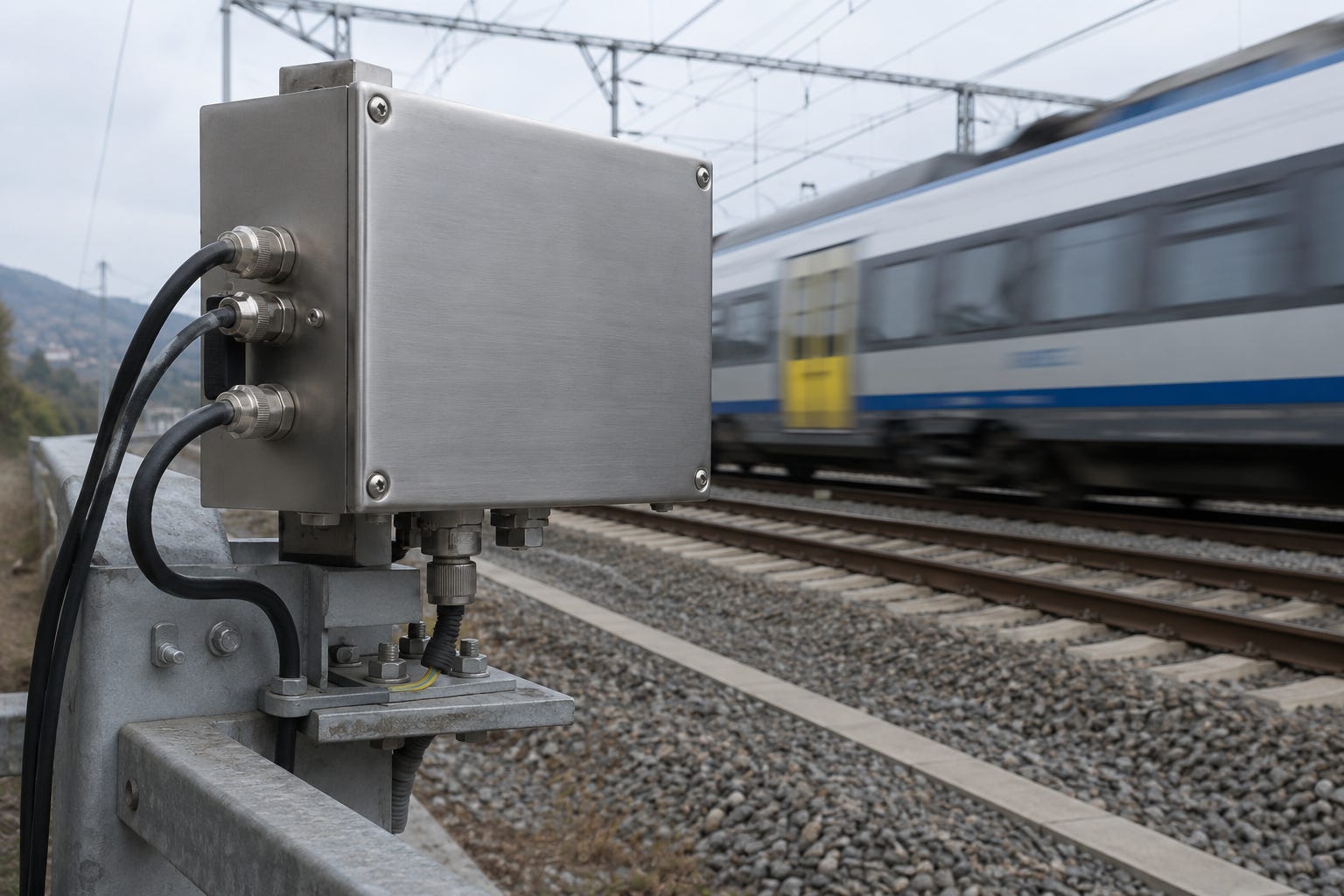
Sensors fill the gaps between those snapshots, collecting data from trackside installations or from instruments mounted on vehicles already running in commercial service.
What the network measures
Measurement in rail covers five principal domains, beginning with track geometry. Track recording vehicles equipped with inertial measurement units and laser sensors measure gauge, alignment, longitudinal level, cross-level and twist, assessed against the EN 13848 standard series, which defines the geometry parameters and the alert, intervention and immediate action limits tied to speed range.
Wheel and axle condition is the second domain. Trackside detectors monitor bearing temperature, wheel impact loads and wheel profile geometry as trains pass at speed, while onboard accelerometers on axle boxes detect the vibration signatures of surface defects and developing bearing faults between fixed wayside measurement points.
Continuous monitoring
Structural integrity covers bridges, tunnels and embankments, monitored with strain gauges, accelerometers and fibre-optic sensing systems. Distributed optical fibre sensors can function as a continuous measurement element over kilometre-length spans, detecting strain and temperature simultaneously, from which load effects on the structure can be derived.
The stakes are considerable: a mapping exercise completed in 2007 put the European bridge stock at more than 300,000 structures, over 220,000 of them covered by the underlying dataset, with more than 35% already over 100 years old at that time (European Commission Sixth Framework Programme, Sustainable Bridges project).
Ageing stock of this kind, carrying axle loads and traffic frequencies higher than its original design assumptions, is exactly where continuous monitoring earns its place alongside periodic visual inspection.
Current collection and the train itself
Current collection is the fourth domain: on electrified networks, the dynamic interaction between pantographs and overhead contact wires is monitored for contact force, arcing and wire wear. Instrumented pantographs carry force transducers; dedicated measurement vehicles scan contact wire geometry at line speed.
The fifth domain sits inside the train itself. Pressure and temperature sensors embedded in braking, traction and cooling systems provide continuous operational data that feeds cab diagnostics and remote condition monitoring platforms.
Data integration
The value of sensor data depends on what happens after collection. Raw measurements require filtering to remove electrical and mechanical noise, threshold logic to generate alerts, and trend analysis to distinguish normal wear from developing faults.
Most European operators maintain separate data streams for wayside and onboard measurements. Correlating these — matching a wheel impact event detected trackside with the axle box acceleration signal logged onboard — remains technically demanding.
The trend is toward centralised condition monitoring platforms that aggregate multiple sources. Standardisation of data formats across suppliers and infrastructure managers is incomplete.
Regulatory context
European legislation ties measurement to mandatory maintenance obligations. Commission Regulation (EU) 1299/2014 (the Infrastructure TSI) sets immediate action limits on track geometry defects that measurement systems must resolve, with alert and intervention limits left to each infrastructure manager’s own maintenance regime.
Commission Regulation (EU) 1301/2014 (the Energy TSI) sets acceptance requirements for overhead contact line geometry and current collection quality, verified through measurement to EN 50317.
The EU-Rail Joint Undertaking — the European partnership on rail research under Horizon Europe — covers sensing and condition monitoring within its Flagship Area on intelligent and integrated asset management, developed further through the FP3-IAM4RAIL project. The work spans sensor platforms, condition monitoring architectures and onboard diagnostics development.
The measurement challenge
The railway environment is hostile to precision instrumentation. Vibration on axle boxes and bogies, electromagnetic interference from traction return currents, temperature ranges spanning more than 100°C, and exposure to moisture and contamination all affect sensor performance and calibration stability.
Equipment must satisfy EN 61373 (shock and vibration for rolling stock), EN 50155 (electronic equipment for rolling stock) and EN 50121 (electromagnetic compatibility) before deployment on or near trains.
Go deeper:
Accelerometers and inertial sensors